ESP32 Basics - Preface
It is a nature of the ESP32 thing (also other microcontroller units) that you must modify the here supplied source code for your device.
Available free IO pins, I2C and SPI Interface pins, TFT Resolution, Touchscreens, Breakout Boards...
To let the mess perfect the expansions pinheads of a Development Board must not match the GPIO pin of the ESP32 microcontroller unit, i.e.
the expansions interface pin 23 of the WT32-SC01 Development Board is NOT connected to GPIO 23 of the ESP32-Wrover mcu, it is connected to GPIO 12 of the ESP32-Wrover mcu.
Examples:
The I2C_SDA / I2C_SCL Pins of the WT32-SC01 Development Board are GPIO 18 and GPIO 19. For the LILYGO TTGO-T-Display Development Board the I2C_SDA / I2C_SCL pins are the default GPIO 21 and GPIO 22.
The speed of a motor, the PWM signal from the mcu must be connected to the correct ENABLE pin of the L298 motor driver.
The speed of a motor, the PWM signal from the mcu must be connected to the correct IN pin of the DRV8833 motor driver.
Sometimes a timing must be adjusted, i.e the ESP-NOW message delay in the here published Robot One WR32-SC01 transmitter software or the PWM frequence in the Robot One LILYGO TTGO-T-Display receiver software to match the gear/motor characteristics.
Conclusion:
A microcontroller unit isn't a PC or a Smartphone where Microsoft, Linux or Android manage all that things.
A microcontroller software isn't a point and click software. Keep that in mind.
Note:
All esp32 source code on this page is written for and tested with the WT32-SC01 Development Board and / or the LILYGO TTGO-T-Display Development Board!
ESP32 Basics - Microcontroller Unit
- There are different hardware versions of the ESP32 microcontroller unit available. Download the correct documentation for your device.
- GPIO 0, GPIO 2, GPIO 4, GPIO 5, GPIO 12 and GPIO 15 are strapping pins that bring the ESP32 into bootloader or flash mode while booting. Connecting something to it during boot which pull the pins into the HIGH or LOW state can lead to unexpected behavior.
- The ADC2_CHx pins cannot be used as analog inputs when WiFi is active.
- GPIO 34 - 39 are inputs only, no internal pull-up or pull-down resistor available on these pins.
- Using GPIOs as an input must be enabled with INPUT_PULLDOWN when using the ESP32.
- This are the DEFAULT esp32 pins for the HSPI, the VSPI and the I2C interface, which must not match the configuration of a Development Board:
| HSPI_MISO | = GPIO 12 |
| HSPI_MOSI | = GPIO 13 |
| HSPI_SCLK | = GPIO 14 |
| HSPI_CS | = GPIO 15 |
| VSPI_MISO | = GPIO 19 |
| VSPI_MOSI | = GPIO 23 |
| VSPI_SCLK | = GPIO 18 |
| VSPI_CS | = GPIO 5 |
| I2C_SDA | = GPIO 21 |
| I2C_SCL | = GPIO 22 |
ESP32 Basics - Development Boards
Before buying a ESP32 development board be sure that all necessary drivers (TFT, Touchscreen, USB...) are available and working. Google it ('chip name' driver).
If you are a newbie or if you want to play around with the ESP32 i suggest to buy an ESP32 development board with integrated wlan/bluetooth and a capacitive touchscreen.
Hint: A touchscreen is a very, very nice feature, no external buttons necessary!
ESP32 Basics - USB Driver
For uploading software from Windows / Linux to the ESP32 microcontroller unit an USB driver is required, depending to the USB chip on the ESP32 development board.
ESP32 Basics - IDE for Software Development
There are several IDE's available, Arduino, PlatformIO, Plugins for Visual Studio...
The Arduino IDE is a good choice for the first steps and for small / medium projects (last Arduino version working with Windows XP 32 Bit is version 1.8.9).
Install the Arduino ESP32 support and install a graphics and fonts library of your choice.
Two of them are listed below.
ESP32 Basics - Power Supply is 3.3V, max. IO Pin Voltage is 3.3V
Never connect 5V to an ESP32 IO pin!
There is an espressif statement available that the esp8266 is 5V tolerant but the esp32 isn't!
Be carefull if you use 5V moduls, i.e. the echo output pin voltage of most ultrasonic moduls is up to 5V.
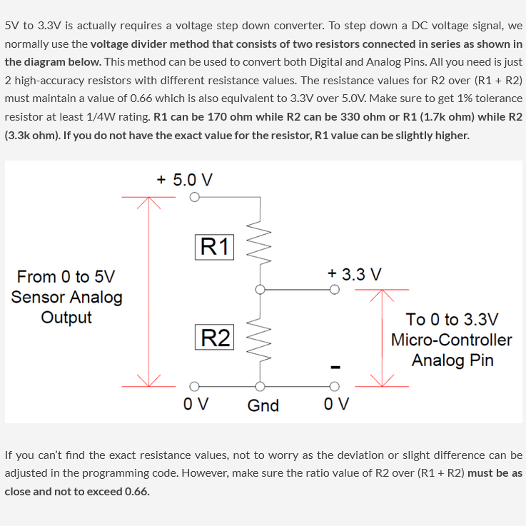
If the output pin voltage of a modul is 5V you should modify the modul output pin voltage using a simple voltage divider or a level shifter modul as shown below.
ESP32 Basics - Links to startup